This is an old revision of the document!
E-Logic - E-Plex Software Suite
Compatibility
E-Logic is compatible with the following operating systems:
- Windows XP
- Windows XP Embedded 1)
- Windows Vista
- Windows 7
- Windows 7 64-bit
Links
E-Logic Software Download Page
Member resources (you must be logged in to access this page )
)
FAQs
General
Where can I download the driver for the E-plex USB to serial converter?
- The driver can be found in the USB sub-folder of the E-Logic installation called (C:\ELogic\USB).
- The latest signed driver can be downloaded from http://www.ftdichip.com/Drivers/CDM/CDM20814_Setup.exe
How do I set a module's Unique Properties that are saved with the E-Logic design?
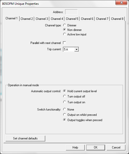
Some modules have unique properties that are saved in the design and automatically programmed to the module when you do a program all. These properties can be found by right-clicking on the module and selecting Unique Properties… from the menu. The next time you program this module, these properties will be updated. For some modules, properties like the current trip set point are also linked with the module test program. If the properties are changed in the module test program, they are automatically changed in the unique properties window.
Do objects need to have all their pins connected to something?
E-Plex modules do not need to have all their pins connected to a wire in order for the design to compile. On the other hand, logic objects do require that all pins have a wire attached to them. On the “input” side (left side) the wire must have a source and be connected to the output some of other logic or modules. On the “output” side (right side) the wire does not need to go anywhere.
How do I determine the address of a wire?
After the design has been compiled and the E-Plex Interface has been opened, you can determine the address of a wire by moving your mouse over it. When the mouse is moved over the wire, you can find the address and bits in the status bar at the bottom of the screen. For wires that are attached to the “output” side (right side) of E-Plex modules, this address will not change so long as the address of the module does not change. For wires that are attached to the output side of logic, you will need to attach an ADDRESSOUT object (CONSTANTS group) to the wire to force it to an address. This address can then be used in the layout software for the LCDs.
What do you mean by analogue value? I thought this was a digital multiplexed system?
All values on the E-Plex bus are technically digital. The term analogue is used to refer to values that have more than one bit of information. This includes, but is not limited to, voltages, currents, RPMs, temperatures and other values. A single digital value can only be off or on. Please note that off, false, and zero are all synonymous. So are on, true, and one.
Why do addresses in E-Logic start at 10?
Addresses 1 to 9 are reserved for backwards compatibility.
I ran the E-Server software and nothing happened.
The E-Server software is most likely minimized to the tool bar. Check for a red, green, or yellow circle at the bottom-right of your Windows desktop.
Why are my DC voltages reading ten times what they should be?
In both the E-Layout and GPC Layout software, the tenths flag needs to be checked for DC voltages. This includes DC voltages being read from a 331BMI, 400ECM, and 411BAM. This will cause the voltage to be displayed as 12.6 instead of 126.
Why are my DC amperages pegged at 99?
In both the E-Layout and GPC Layout software, the negative flag needs to be checked for DC amperages. It is also important that the bits be set to 10, even if the value is being processed by logic. The number of bits tells the display software where to look for the negative sign.
How do I make an element show up on all pages in the layout software?
Set the page value to 0 to make an element show up on every page.
What are the RGB values for the button colours in the layout editor?
| Name | Sample | RGB | |
|---|---|---|---|
| Decimal | Hex | ||
| Dark red | Sample | 128, 0, 0 | 800000 |
| Dark green | Sample | 0, 128, 0 | 008000 |
| Dark blue | Sample | 0, 0, 128 | 000080 |
| Dark yellow | Sample | 128, 128, 0 | 808000 |
| Dark cyan | Sample | 0, 128, 128 | 008080 |
| Dark purple | Sample | 128, 0, 128 | 800080 |
| Dark brown | Sample | 128, 64, 32 | 804020 |
| Dark grey | Sample | 64, 64, 64 | 404040 |
| Red | Sample | 255, 0, 0 | FF0000 |
| Green | Sample | 0, 255, 0 | 00FF00 |
| Blue | Sample | 0, 0, 255 | 0000FF |
| Yellow | Sample | 255, 255, 0 | FFFF00 |
| Cyan | Sample | 0, 255, 255 | 00FFFF |
| Purple | Sample | 255, 0, 255 | FF00FF |
| Brown | Sample | 255, 128, 64 | FF8040 |
| Grey | Sample | 128, 128, 128 | 808080 |
| Black | Sample | 0, 0, 0 | 000000 |
| White | Sample | 255, 255, 255 | FFFFFF |
| Off white | Sample | 212, 212, 212 | D4D4D4 |
| Light black | Sample | 32, 32, 32 | 202020 |
| Royal blue | Sample | 60, 120, 255 | 3C78FF |
| Coral pink | Sample | 255, 100, 100 | FF6464 |
| Golden rod | Sample | 231, 177, 66 | E7B142 |
| Light sea green | Sample | 0, 152, 146 | 009892 |
| Chocolate | Sample | 133, 96, 60 | 85603C |
What calibration information is embedded in the E-Logic software?
The following gets embedded into E-Logic software:
- Module trip current settings
- TPS regions
- TPD regions
- RSP colours
- 500CCM side panel touch regions
Performing a Program module or Program All updates the modules stored information.
Here’s what doesn’t get embedded:
- Calibration in any module
- Tables in any module
- 400/450ECM regions
This information must be entered via the E-Plex interface.
How do I use the Indexed Text element in the layout software to display more than 2 different messages?
You must set the number of bits to between two and four. One bit allows you to display two different messages: a message for off/false/zero, and a message for on/true/one. Two bits allow you to display four different messages, three bits allow you to display eight different messages, and four bits allow you to display up to sixteen different messages. Currently you have to use digital ADDRESSOUT objects at consecutive addresses to do this. For example, three different ADDRESSOUT objects at addresses 45, 46, and 47 would allow you to display up to eight different messages. To determine which message will be displayed at any given time, you have to convert the digital values to binary. The first address (45) is the 1's digit, the second (46) is the 2's digit, and the third (47) is the 4's digit. (If there were a fourth bit, it would be the 8's digit) If all three are true, then the sum will be 7 and it will display the message defined for “Text When Value = 7:”
Alternately, you can use the INDEX4, INDEX8, or INDEX16 objects to drive an analogue value. The output of these objects changes depending upon which of their inputs is true, with the higher numbers having priority. You would then attach a single ADDRESSOUT object to the output of the INDEX, and use the address of that in your layout design. Even though the ADDRESSOUT object will reserve 16 bits (making it less efficient than the above method), you will still want to set the layout to 2, 3, or 4 bits respectively depending upon how many messages you need.
My ADDRESSOUT object is giving me a weird "multiple of eight" error.
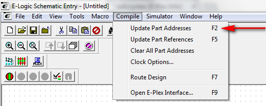
ADDRESSOUT objects that are attached to analogue wires must have addresses that are multiples of eight, plus one. They also must be greater than 10. (17, 25, 33, 41, 49, etc…) The best way to do this is to let the software automatically assign the address for you. Make sure the address field is clear, and use the Update Part Addresses tool.
Logic objects
What is the resolution of the TIMER objects DELAYON, DELAYOFF, and PULSEON?
The resolution of these timers is 0.125s (1/8s). The maximum range of these timers is 2.27 hours. Longer durations can be achieved by cascading timers together. The timer value can be in units of s for seconds, m for minutes, or h for hours.
Why can't I attach an ADDRESSOUT object to the output of an E-Plex Module?
The addresses of wires on the output (right-hand) side of E-Plex modules are automatically set based upon the address of the module itself. These cannot be changed by an ADDRESSOUT object. If you need to redirect one of these wires to a new address, you must first pass it through a BUFFER or BUFFERANALOG object.
What is the truth table for object X?
Please refer to the list of truth tables.
How do the maths objects work?
Please refer to the maths objects page of the E-Logic manual.
E-Plex interface
A module functions using its test program, but not when it is streaming. How can I determine if the module is streaming?
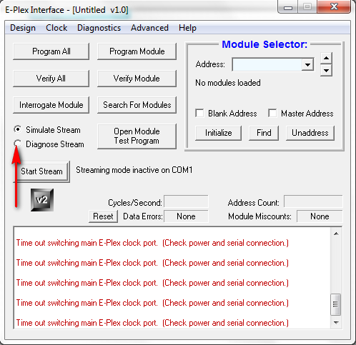
With the E-Plex Interface open, first stop streaming. Then click on Diagnose Stream, which can be found just above the Streaming button. The Responding Modules window should appear. Start streaming again and this window should indicate which modules are streaming and which are not responding. An “OK” indicates that the module is responding, whereas a “None” indicates that there is no response.
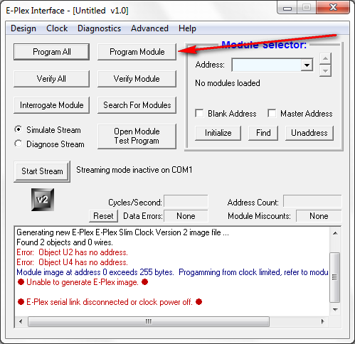
What happens when I program a module from the E-Plex Interface?
When you click on Program Module, you download the information that the module needs to stream correctly. This information changes any time the design changes, which is why a Program All needs to be done anytime you change the logic.
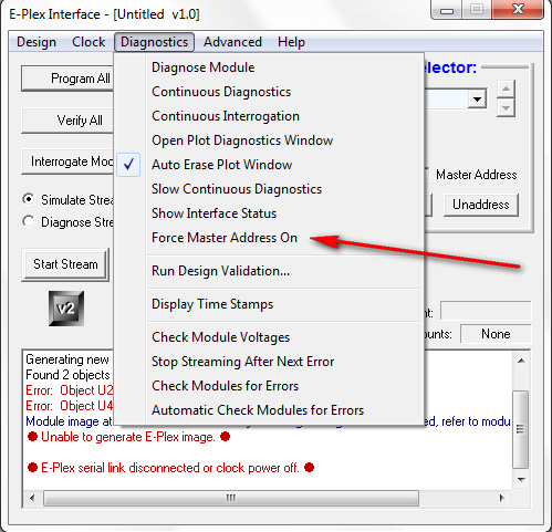
How can I turn on the master address if the module's ID does not match?
You can go to the Diagnostics menu in the E-Plex Interface and select Force Master Address On. Please be sure that only one module is connected to the bus when using the master address.
I am unable to stop streaming, or everything fails when I try to program modules, what's wrong?
Check that the E-Logic design that is being used contains the correct type of clock module. If the wrong clock has been used, E-Logic will not be able to talk to the E-Plex system.
When I interrogate or initialise some modules, E-Logic reports: "Time out reading module key at address XX!" Is my module faulty?
Probably not. As part of the interrogate and initialise procedures, E-Logic requests a piece of information called the module key. However this feature has not always been present, and not all devices have been updated to support the command. This change is not critical, so it is only being made to existing firmware when other changes are required. If you receive this message, please check the wiki page for that module to make sure that this response is expected for the firmware version you are using. If this is not an expected response, then your module may be faulty.
Simulator
What do all these colours mean when the E-Logic simulator is on?
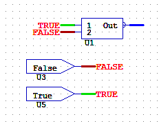
Red indicates a digital wire that is false. Green indicates a digital wire that is true. Blue indicates an analogue wire. To view an analogue, mouse over it and check the status. Also, you can left click on the wire to pop up a window that displays the value.
Why are some of my wires yellow with the simulator on in hardware simulation mode?
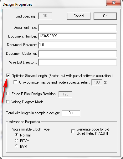
You have Optimise Stream Length on. This option can be set by going to View→Design Properties. You will have to recompile the design after changing this option. With this feature on, the clock module only returns the basic simulation information. Any wires that it are optimised out will show as yellow. All the logic is still being executed, but the data is not being returned to the PC. This makes the clock stream faster and is the recommended mode for production. However, when debugging the system it is often useful to turn this feature off so you can see all the logic. It is important to note that after changing this option, you will need to do a Program All for the changes to take effect.
How do I change values with the simulator on?
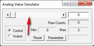
To change a digital value, simply left click on it to toggle it. To change an analogue value, left click on it to bring up the Analogue Value Simulator window. Make sure Control is selected, and you can use the slide to change the value. You can only change the values that are the outputs of modules. (Inputs from the real world) When simulating through hardware, you can only change the outputs of modules that are not present on the bus.
What is the difference between software and hardware simulation?
With software simulation, you are not connected to a clock module (400ECM) and the E-Logic software running on PC is simulating all of the logic. With hardware simulation, you are connected to a clock module that is streaming. The values you see are being updated in real time and represent what is currently happening on the bus. You are actually monitoring the stream in this mode. If you press a button on a switch panel, you will be able to see it in the simulator and watch the logic execute. Any time the E-Plex Interface is open, you are using hardware simulation. If the status line does not say “Streaming…” then nothing is being simulated.
Sometimes when I close the E-Plex interface whilst simulating, E-Logic becomes unresponsive. How do I prevent this?
When you close the E-Plex interface during hardware simulation, E-Logic automatically switches to software simulation. When it does this, you will get a message telling you what it has done, with the option to suppress that message in the future.
Under some circumstances, the message box is displayed behind the main E-Logic window. If this happens it will appear as though E-Logic is completely locked up, as the main window will not allow any interaction until the message box has been dismissed. In order to get around this, use alt+tab on the keyboard to switch to another application, then press alt+tab again to switch back to E-Logic. You should now find that the message box is on top of the main window and can be dismissed. Clearing the tick that says “Show these messages” will prevent the problem from occurring in the future.
3rd party applications
How do I control ...
E-Logic includes an OPENAPP object that allows you to run another Windows application- this could be an operating manual for a boat in pdf format, for example. You specify the path to the application in the properties of the OPENAPP object, and then make its input true to run it.
There is a useful application called NIRCMD that lets you control various Windows features, such as turning the monitor off.
Optimisations
My software has exceeded the maximum number of addresses/contains a lot of logic objects and runs quite slowly. Is there anything I can do to reduce its size/make it run faster?
E-Logic is capable of optimising a design in order to reduce the amount of information that needs to be sent over the bus. By default, optimisations are disabled as they make it a little harder to test the software. However, once a design reaches a certain size, it is necessary to enable optimisations in order for it to run. To enable optimisations, select Design Properties from the View menu. In the dialogue box that appears, tick the box labelled Optimize Stream Length, and then click OK. Optimisations are now enabled, and your stream length should be reduced.
If optimisations are so good, why are they disabled by default?
When you create a design, every wire is assigned an address. The more addresses a system has, the slower it runs. There is also an upper limit to the number of addresses that the system can have. When optimisations are enabled, E-Logic looks at all of the addresses to determine which ones are actually used on the bus, and which ones are only used internally within the clock. If an address (wire value) is only used internally, that address is removed. The value is still calculated in the clock, but it never gets sent over the network. Because less data is sent on the bus, the system runs faster. However, because that value is not sent on the bus, it cannot be used in simulations. If you try to simulate a design with optimisations enabled some of the wires will be yellow; these are the optimised wires and it is not possible to read their values, because they are not sent on the bus.
I am trying to test my design using the simulator, but the wire I need to watch is optimised. I cannot turn off optimisations for this design, is there anything else I can do?
It is possible prevent E-Logic from optimising a specific wire by connecting that wire to an ADDRESS object (CONSTANTS group). Once testing has been completed, the ADDRESS object can be deleted in order to allow E-Logic to optimise the wire again.
Layout Editor
How do I create a custom button?
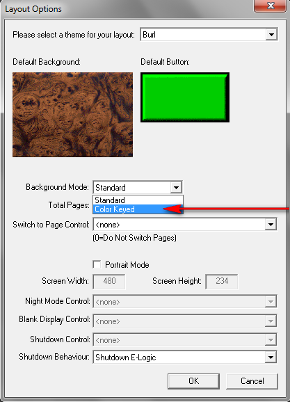
Custom buttons can be created in integrated layout when Color Keyed background mode is used. This is the method where a background image must be downloaded for each page on the display. Two images must be created to import a custom button graphic. The first is the full color image and the second is the mask. Both images must be saved as 24-bit bitmaps before being imported. For examples, please look at the following two files:
C:\ELogic\Template\Cream Button.bmp
C:\ELogic\Template\Cream Button Mask.bmp
The first bitmap is the full color image and the second is the mask. The full color image is what the button will actually look like on the screen. The mask is used to define two things, the opacity channel and the color key channel. The white pixels in the mask control the opacity (opposite of transparent). The cyan (blue-green) pixels in the mask control the color keying.
Black pixels in the mask will be transparent to the background and white pixels will be opaque (the color of the full color image). Gray pixels represent the varying degrees of transparency. The cyan colors in the mask represent the color keyed portion of the button. These pixels will change dynamically based upon the input of the button and the color settings in the layout. Different intensities of cyan will correlate to different intensities of the selected color. However, it is important that the color keyed cyan portion does not go to totally black or else this will be interpreted as transparent.
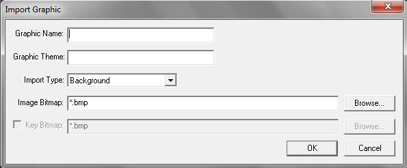
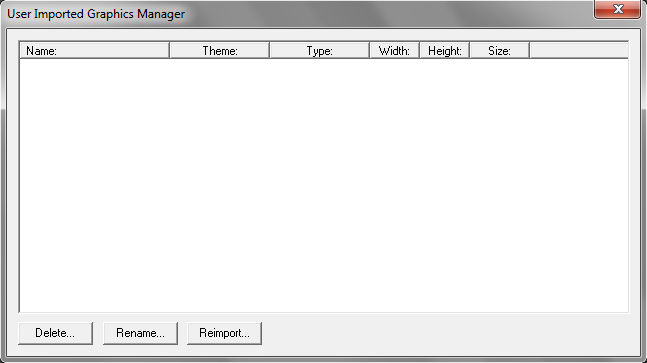
Once the images have been created, they can be imported through the layout editor. Go to Design→Import Graphic… Give the graphic a name and an optional theme. Select the import type as Button. In the Image Bitmap field, browse for the full color bitmap created above. Enable the check for the Key Bitmap, and browse for the color key mask created above. Click on OK, and the button is imported and ready to use. If you want to change or update the button graphics at a later time, you can go into Manage Graphics… and re-import the bitmaps.
This same technique can be used for tanks, meters, and gauges, however the location of the drawn on elements (such as the horizontal bar graph on a “Meter” or the needle on a “Gauge”) cannot be changed. You can however do custom color keyed vertical tanks using this technique. See Oval Tank.bmp and Oval Tank Mask.bmp for an example of how to do this.
An alternate method for accomplishing this is to create a unique background for each page using 3rd party software such as Adobe Photoshop. All of the buttons and graphics will be part of this image and the embedded display software will only draw things that change on top of the static background. Each page will have to be imported separately into the software as a 24-bit “Background” bitmap from the Design→Import Graphics menu.
The “Background Button” and “Background Tank” elements are most commonly used in this technique. These elements will color key off of a user defined (Key Color: in drop down box of the Properties window) color in the background and will change this color based on the Input wire.
Later firmware versions also support the “Background Gauge,” where the embedded display only draws the needle and the rest of the gauge is part of the background image.
Can I use my own fonts in my layout?
Integrated layout supports custom fonts through an INI file in the E-Logic directory. Only designs that use color keyed mode or PC-based designs can use the custom fonts. Designs that go on embedded displays (as opposed to PCs) can only use the custom fonts in static elements that do not change (e.g. static text, button text).
Here are the contents of a sample file customfonts.ini in the C:\ELogic directory:
MyFont1,Courier New,12
MyFont2,Times New Roman,16
MyFont3,Arial Bold,12
#
Each line represents one custom font. There are three values, separated by commas. The first value is the user name of what the font will be. This is what you will select out of the Font drop down box in the layout editor. The second value is the face of the font, and the third value is the point size of the font. The # on the last line indicates that there are no more entries in this file.
Once the fonts are used in a design, the order of the entries is important. New entries should only be added to the bottom of the file. The user must also manually copy this INI file to any other installations of E-Logic on different PCs that the layout is to be opened on.
Common Error Messages
The following error messages may be encountered in E-Logic:
Insufficient Data to Process Stream
Insufficient Data to Process Stream x of x may appear in the E-Plex Interface window when running in interface mode. If connected to the clock via a USB to serial converter, could indicate that data is not being transmitted through the converter at a sufficient rate or without buffer overflow. You may also find that the interface screen will not operate correctly, certain switches etc may not operate. In some cases the unit will continue to operate. The only solution is to use an alternative USB to serial converter preferably the type that uses an FTDI chipset.
Bootloader
I accidentally loaded the wrong firmware into a module, and now it won't communicate. Is there any way to fix this?
Usually, you can power cycle the module and it will revert to bootloader mode. After power cycling the modules, when you interrogate you will see the message similar to the following:
Module at address 58 identified as: *Enabled* Boot Loader Mk2 [v2.02 revZ]
It may be necessary to enable the master address in order for the module to respond to interrogation, in which case you will have to disconnect any other modules from the bus. Once the module has been located, it can then be bootloaded as normal.

