Gates Objects
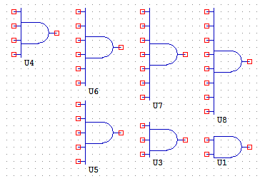
AND2, 3, 4, 5, 6, 7, 8
AND takes from two to eight digital inputs and “ANDs” them together into a single digital output. In order for the output of an AND gate to be true, all of its inputs must be true. AND2 has two inputs. AND3, 4, 5, 6, 7 and 8 are similar, just with 3, 4, 5, 6, 7 and 8 inputs respectively.
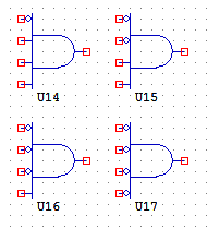
AND2N1, 2N2
AND2N1 is a logical AND gate with 2 inputs and 1 inversion. AND2N2 is similar, just with 2 inversions.
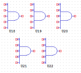
AND3N1, 3N2, 3N3
AND3N1 is a logical AND gate with 3 inputs and 1 inversion. AND3N2 and 3N3 are similar, just with 2 and 3 inversions respectively.
AND4N1, 4N2, 4N3, 4N4
AND4N1 is a logical AND gate with 4 inputs and 1 inversion. AND4N2, 4N3 and 4N4 are similar, just with 2, 3 and 4 inversions respectively.
AND5N1, 5N2, 5N3, 5N4, 5N5
AND5N1 is a logical AND gate with 5 inputs and 1 inversion. AND5N1, 5N2, 5N3, 5N4 and 5N5 are similar, just with 2, 3, 4 and 5 inversions respectively.
BUFFER
BUFFER simply copies its input to its output. The buffer does not change the value at all. The most common use for a buffer is to give the same wire two different names. Note: The BUFFER object is easy to confuse with the NOT gate, because the symbols are similar. The BUFFER object does not have a circle on its output pin.
BUFFERANALOG
BUFFERDELAY
BUFFERDELAY behaves like the BUFFER object, except that there is a 1-stream delay before the input is copied to the output.
NAND2
NOR2
NOT
NOT gate simply inverts a digital wire from true to false or from false to true. Note: The NOT gate is easy to confuse with the BUFFER object, because the symbols are similar. The NOT gate has a circle on its output pin.
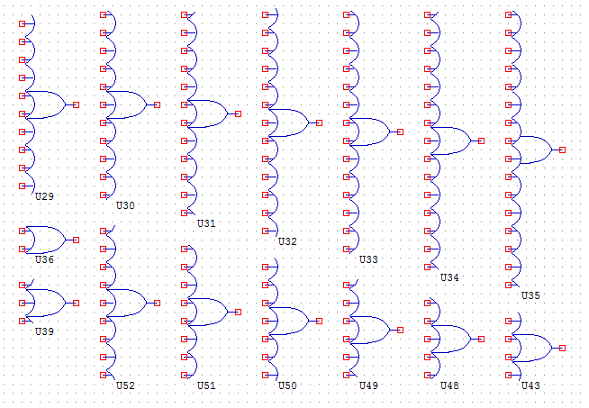
OR2, 3, 4, 5, 6, 7, 8, 9, 10, 11, 12, 13, 14, 15, 16
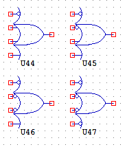
OR gate is similar to the AND gate. It takes from two to eight digital inputs and “ORs” them together into a single digital output. In order for the output of an OR gate to be true, one or more of its inputs must be true. OR2 has two inputs. OR3, 4, 5, 6, 7, 8, 9, 10, 11, 12, 13, 14, 15 and 16 are similar, just with a respective number of inputs.
OR2N1, 2N2
OR3N1, 3N2, 3N3
OR3N1 is a logical OR gate with 3 inputs and 1 inversion. OR3N2 and OR3N3 are similar, just with 2 and 3 inversions respectively.
OR4N1, 4N2, 4N3, 4N4
OR4N1 is a logical OR gate with 4 inputs and 1 inversion. OR4N2, 4N3 and 4N4 are similar, just with 2, 3 and 4 inversions respectively.
XOR2, 3, 4, 5
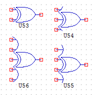
XOR gate is an “eXclusive OR” gate. It takes from two to four digital inputs and XORs them together into a single digital output. In order for the output of an XOR gate to be true, an odd number of inputs must be true. XOR2 has two inputs. XOR3, 4 and 5 are similar, just with 3, 4 and 5 inputs respectively.

